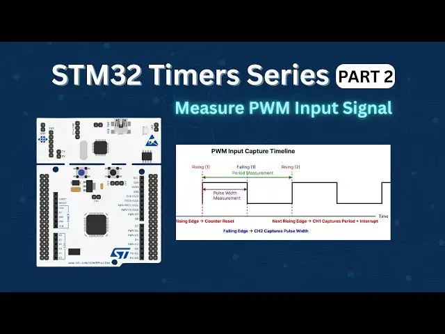

STM32 Timers (PART 2): How to Measure PWM Input Signal with STM32 Timer
Jul 31, 2021

Learn how to use STM32 PWM Input mode to accurately measure the frequency and duty cycle of an incoming PWM signal using timer input capture.
🔨Calculate the ARR and CCR values for the STM32F4 Timers using the STM32F4 PWM Tool : https://controllerstech.com/tools/stm32f4-pwm-calculator/
📁 Download project files & article:
STM32 Timer PWM Input ☞ https://controllerstech.com/pwm-input-in-stm32/
📁 STM32 Tutorials ☞ https://controllerstech.com/stm32-tutorials/
📁 ControllersTech Home ☞ https://controllerstech.com/
▶︎ Related Videos:
1️⃣ STM32 Timer PWM Output (Part 1) → https://youtu.be/OwlfFp8fPN0
2️⃣ STM32 Timer Encoder Mode (Part 3) → https://youtu.be/xqzWQgpqHmI
3️⃣ STM32 Timer Playlist → https://www.youtube.com/playlist?list=PLfIJKC1ud8gjLZBzjE3kKBMDEH_lUc428
🔔 Subscribe for more STM32 tutorials! 👍 Like & share to help others.
💡 Share this video for STM32 Timer tips!
#STM32 #EmbeddedSystems #PWM #InputCapture #Microcontroller #ElectronicsEngineering #STM32Tutorial #ControllersTech #Timer #DutyCycle #FrequencyMeasurement #EmbeddedProgramming #ARM #FirmwareDevelopment #HALLibrary
________________________________________________________________________________________
******* SUPPORT US *******
🎁 Support My Work on Patreon: https://www.patreon.com/5065726/join
Show More Show Less